Blog
Practical Guide
The form of internal separation you specify controls who can safely work on your switchboard while it stays energized. Choose wrong, and you are either overspending or creating risk.
When specifying a low-voltage switchgear assembly, most attention goes to rated current, short-circuit withstand, and protection degree. But there is another parameter that directly affects both operational safety and maintenance flexibility, which is the form of internal separation.
IEC 61439-2 defines four forms of internal separation: Form 1 through and Form 4, each with further subdivisions. These forms describe how the busbars, functional units, and cable termination compartments inside a switchboard are physically separated from each other.
It’s not purely a technical choice. The choice determines what maintenance work can be performed. At the same time, adjacent circuits remain alive; how faults propagate within the assembly ultimately determines the operational downtime the installation will require over its lifetime.
This article explains each form, when to specify which, and the practical trade-offs involved..
Table of Contents
SIVACON S8: Inside a Type-Tested System
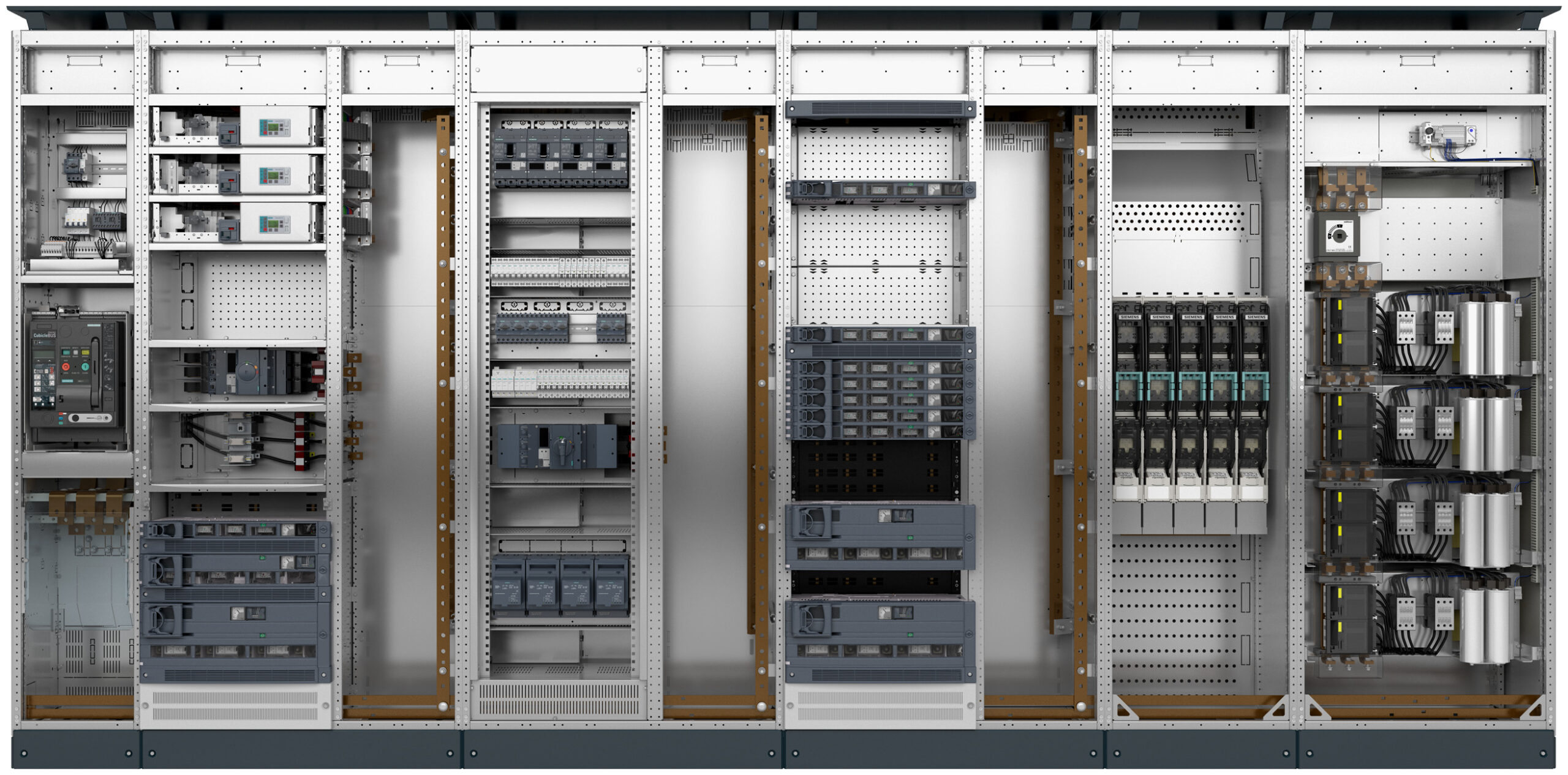
Hover over a section above to see what it does.
What is internal separation?
Internal separation refers to the physical subdivision of a switchgear assembly into distinct zones using metallic or non-metallic barriers and partitions. The goal is threefold: to protect personnel from contact with live parts during maintenance, to limit the propagation of internal faults (including arc faults) between functional units, and to allow intervention on one part of the switchboard without de-energizing the entire assembly.
IEC 61439-2 defines the rules for internal separation. According to the standard, three elements can be separated from each other:
Busbars: The main power distribution conductors running through the assembly.
Functional units: The individual circuit modules (breakers, contactors, starters, fuse switches) that connect to the busbars.
Terminals for external conductors: The cable connection points where incoming and outgoing cables are terminated.
The form is defined by the decision on how these three elements are separated.
The four forms of separation
Form 1: There is no internal separation
This is the simplest arrangement. There are no barriers or partitions inside the assembly. Busbars, functional units, and terminals all share the same space. Any work inside the switchboard requires complete de-energization.
Form 1 is appropriate for small distribution boards and applications with sporadic maintenance, where a complete shutdown is acceptable. This is the most economical option with the most compact footprint.
Form 2: Separation of busbars from functional units
Form 2 introduces the first level of separation, where the busbars are physically separated from the functional units.
Form 2a: Busbars are separated from functional units, but the terminals for external conductors are not separated from the busbars. Separation is typically achieved by insulated coverings.
Form 2b: Busbars are separated from functional units, and terminals for external conductors are also separated from the busbars. This is achieved using rigid metallic or non-metallic barriers.
Form 2 allows basic maintenance on functional units without direct exposure to live busbars. However, functional units are not separated. They are working on one unit that still presents a risk to adjacent units.
Form 3: Separation of functional units from each other
Form 3 adds a critical capability: individual functional units are separated from each other, in addition to the busbar separation already present in Form 2.
Form 3a: Busbars are separated from functional units. Functional units are separated from each other. But terminals for external conductors are not separated from the busbars. They share a common cable compartment.
Form 3b: Busbars are separated from functional units. Functional units are separated from each other. Terminals are separated from the busbars. However, terminals are in the same compartment as their associated functional unit.
Form 3 is the standard choice for industrial main distribution boards, power control centers, and motor control centers where individual feeders need to be maintained while adjacent feeders remain in service. Form 3b is widely considered the minimum specification for any installation with significant downtime costs.
Form 4: Complete compartmentalization
Form 4 provides the highest level of internal separation. Every functional unit, every terminal compartment, and the busbars are all physically isolated from each other.
Form 4a: Busbars are separated from functional units. Functional units are separated from each other. Terminals for external conductors are in their own compartments. However, these compartments are integrated with the functional unit they serve (typically sharing a door or access panel).
Form 4b: Busbars are separated from functional units. Functional units are separated from each other. Terminals for external conductors are completely separate in individual compartments. Each has its own access point, physically independent from the functional unit compartment.
Form 4b has the maximum achievable separation. A maintenance technician can access and work on any individual functional unit or cable termination while every other part of the switchboard remains fully energized and protected. This is essential for critical installations where any downtime is unacceptable. These applications could be data centers, hospitals, process plants, and critical port infrastructure.
Forms of Internal Separation
How to choose the right form
The form specification should be driven by the operational requirements of the installation, not by habit or default.
Several key factors need to be considered:
Will maintenance be performed while the switchboard is energized? If the answer is positive, Form 3 minimum. If individual feeders need to be serviced independently, Form 3b or Form 4.
Is there a sector-specific requirement? Some industries effectively mandate higher forms. Medical facilities (IEC 60364-7-710), data centers (Tier III and Tier IV), and critical infrastructure often require Form 4 on the main distribution.
What is the cost of downtime? For installations where an unplanned shutdown costs tens of thousands of euros per hour, the additional cost of Form 4 pays for itself quickly. For non-critical applications where scheduled shutdowns are acceptable, Form 2 or Form 3a may be sufficient.
What are the available space constraints? Higher forms of separation increase the switchboard’s physical depth and width. A Form 4b panel can be significantly deeper than a Form 1 panel of the same electrical capacity. Confirm that the electrical room or E-House can accommodate the footprint before specifying.
Is arc fault containment a separate requirement? Forms of separation and arc fault ratings are independent properties. A Form 4b switchboard is not automatically arc-fault rated. Arc-fault containment is addressed in IEC/TR 61641 and requires separate testing and verification. Both parameters should be specified independently.
The compact footprint of an E-House is also an advantage in constrained spaces. All equipment is arranged in an optimized layout within a defined steel frame, with everything from busbar support to cable entry points engineered for that specific configuration.
Where conventional wins on space: If you are designing a new facility from scratch with ample floor area, an integrated electrical room gives you more freedom on dimensions. E-Houses can be constrained by transport logistics. Road-transportable units are typically limited to widths of around 3-4 meters (depending on the region), though multi-module configurations can extend this.
Common specification mistakes
Specifying Form 4b on every project regardless of need. Form 4b can significantly increase the cost of a panel, footprint, and lead time compared to Form 1. This is over-engineering for the installations where a complete shutdown for maintenance is acceptable.
Specifying “Form 4” without the suffix. The difference between Form 4a and Form 4b has real cost and construction implications. Always specify the complete designation.
Confusing the form of separation with IP rating. Internal separation (Form) and external ingress protection (IP) are independent parameters. A switchboard can be IP54 externally while being Form 1 internally. Both must be specified.
Confusing the form of separation with arc fault containment. A Form 4b switchboard provides excellent compartmentalization, but this does not mean it will contain an internal arc fault. Arc fault withstand capability per IEC/TR 61641 is a separate verification that must be specified and tested independently.
Specifying Form 1 and then requesting live maintenance access. The construction does not support it. Either change the form specification or change the maintenance strategy.
SIVACON S8 is a type-tested switchgear system that supports internal separation up to Form 4b across all mounting designs. These designs include options such as withdrawable, fixed-mounted compartment doors, and plug-in in-line configurations.
The system achieves Form 4b through a combination of type-tested standard modules, add-on compartmentalization modules, and a patented connection terminal design that places cable terminations in a physically separate cable connection compartment. The vertical distribution busbars are covered to IP2X (test finger-proof), and phase separation is available as an option.
Because every SIVACON S8 configuration has been type-tested under IEC 61439-2, the form of separation is not just a design intent. The form of separation is a verified, documented property of the assembly. This is the major difference between a type-tested system, where separation has been physically validated, and a custom-built panel, where separation relies on the builder’s interpretation of the standard.
For installations that also require arc fault protection, SIVACON S8 has been tested according to IEC/TR 61641 with arc-resistant design, pressure relief systems, and metal-clad compartmentalization, providing both Form 4b separation and arc fault containment in a single system.
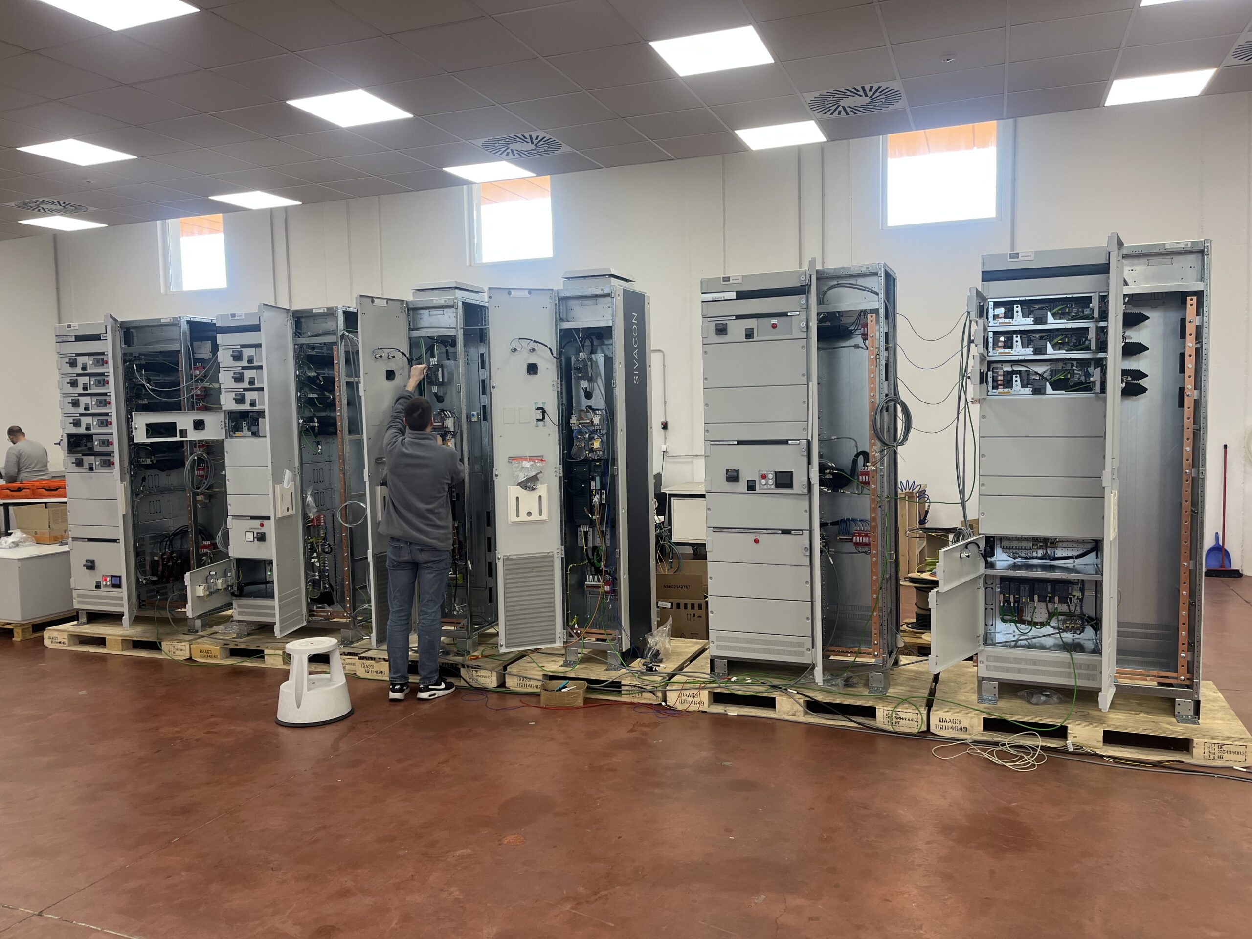
A recent example from our own production: a SIVACON S8 system for an industrial compressor station, configured with Form 4b internal separation, Extended Arc Fault Protection (Class C), and 50 kA short-circuit withstand. The dual MCC configuration (400 A normal load / 200 A essential load) combines withdrawable design for main drives and incoming feeders with fixed-mounted sections for smaller loads, demonstrating how the form of separation integrates with the broader system design rather than existing as an isolated specification.
You might find interesting: